Constructing Inter LAN Routing Network Using Cisco Packet Tracer (Internet System)
INTRODUCTION
Inter LAN routing means to communicate between two different LAN. That is two different LAN will be connected through router. Each LAN will be directly connected to one router. But in the midway there may have many router (as it is inter LAN routing so not only two LAN will be connected there). So we need to fix the way for transferring data packet. And this process is known as “Inter LAN Routing”. If you have 2 or more VLAN there then it is called “Inter VLAN Routing”.
PROCEDURE
In this tutorial Inter LAN Routing procedure will be completed for the network in the attached image:
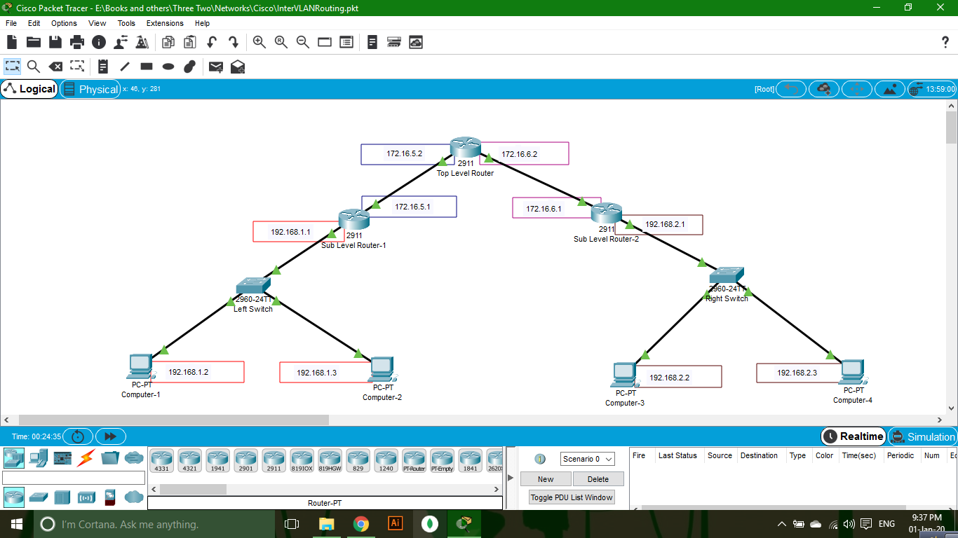
To complete Inter LAN Routing according to this photo you should follow the connection description for each connection devices (Router & Switch).
CONNECTION DESCRIPTION
TOP LEVEL ROUTER
- GigabitEthernet 0/0 – Connected to Sub Level Router-1
- GigabitEthernet 0/1 – Connected to Sub Level Router-2
SUB LEVEL ROUTER – 1
- GigabitEthernet 0/0 – Connected to Top Level Router
- GigabitEthernet 0/1 – Connected to Left Switch
SUB LEVEL ROUTER – 2
- GigabitEthernet 0/0 – Connected to Top Level Router
- GigabitEthernet 0/1 – Connected to Right Switch
LEFT SWITCH
- FastEthernet 0/1 – Connected to Sub Level Router-1
- FastEthernet 0/2 – Connected to Computer-1
- FastEthernet 0/3 – Connected to Computer-2
RIGHT SWITCH
- FastEthernet 0/1 – Connected to Sub Level Router-2
- FastEthernet 0/2 – Connected to Computer-3
- FastEthernet 0/3 – Connected to Computer-4
If you have connected as the description then your network is similar to this network. Now try to configuration. If you configure your network as the tutorial it will be easy for you to proceed.
CONFIGURATION
COMPUTERS
- Computer-1 IP Address: 192.168.1.2
- Computer-2 IP Address: 192.168.1.3
- Computer-3 IP Address: 192.168.2.2
- Computer-4 IP Address: 192.168.2.3
LEFT & RIGHT SWITCHES
No Configuration Needed.
SUB LEVEL ROUTER – 1
- Click on the Router. A popup window will be opened.
- Go to CLI tab in the popup window.
- Click in command box.
- Type “no” to configure manually.
- Press “Enter”.
- To enable the switch give give following command:
enable
- To enable configuration mode give following command:
configure terminal
- To access a 0/0 port (Connected to Top Level Router) give following command:
interface gigabitethernet 0/0
- To enable the port give following command:
no shutdown
- To set the IP Address “172.16.5.1” give following command:
ip address 172.16.5.1 255.255.255.0
- To exit the port give the following command:
exit
- To access a 0/1 port (Connected to Left Switch) give following command:
interface gigabitethernet 0/1
- To enable the port give following command:
no shutdown
- To set the IP Address “192.168.1.1” give following command:
ip address 192.168.1.1 255.255.255.0
- To exit the port give the following command:
exit
- To set the route for a packet from Left Switch to Right Switch give following command (Here “172.16.5.2” is the IP Address of receiver port of Top Level Router and “192.168.2.0” is the IP Address of destination network):
ip route 192.168.2.0 255.255.255.0 172.16.5.2
- To save the configuration give following command:
do write memory
- To exit the configuration mode give following command:
exit
- To exit enable mode give following command:
exit
Sub Level Router -1 Configuration Completed!
SUB LEVEL ROUTER – 2
- Click on the Router. A popup window will be opened.
- Go to CLI tab in the popup window.
- Click in command box.
- Type “no” to configure manually.
- Press “Enter”.
- To enable the switch give give following command:
enable
- To enable configuration mode give following command:
configure terminal
- To access a 0/0 port (Connected to Top Level Router) give following command:
interface gigabitethernet 0/0
- To enable the port give following command:
no shutdown
- To set the IP Address “172.16.6.1” give following command:
ip address 172.16.6.1 255.255.255.0
- To exit the port give the following command:
exit
- To access a 0/1 port (Connected to Right Switch) give following command:
interface gigabitethernet 0/1
- To enable the port give following command:
no shutdown
- To set the IP Address “192.168.2.1” give following command:
ip address 192.168.2.1 255.255.255.0
- To exit the port give the following command:
exit
- To set the route for a packet from Right Switch to Left Switch give following command (Here “172.16.6.2” is the IP Address of receiver port of Top Level Router and “192.168.1.0” is the IP Address of destination network):
ip route 192.168.1.0 255.255.255.0 172.16.6.2
- To save the configuration give following command:
do write memory
- To exit the configuration mode give following command:
exit
- To exit enable mode give following command:
exit
Sub Level Router -2 Configuration Completed!
TOP LEVEL ROUTER
- Click on the Router. A popup window will be opened.
- Go to CLI tab in the popup window.
- Click in command box.
- Type “no” to configure manually.
- Press “Enter”.
- To enable the switch give give following command:
enable
- To enable configuration mode give following command:
configure terminal
- To access a 0/0 port (Connected to Sub Level Router-1) give following command:
interface gigabitethernet 0/0
- To enable the port give following command:
no shutdown
- To set the IP Address “172.16.5.2” give following command (The IP you used in Sub Level Router-1 as receiver):
ip address 172.16.5.2 255.255.255.0
- To exit the port give the following command:
exit
- To access a 0/1 port (Connected to Sub Level Router-2) give following command:
interface gigabitethernet 0/1
- To enable the port give following command:
no shutdown
- To set the IP Address ” 172.16.6.2 ” give following command (The IP you used in Sub Level Router-2 as receiver) :
ip address 172.16.6.2 255.255.255.0
- To exit the port give the following command:
exit
- To set the route for a packet from Left Switch to Right Switch give following command (Here “172.16.6.1” is the IP Address of receiver port of Sub Level Router-2 and “192.168.2.0” is the IP Address of destination network):
ip route 192.168.2.0 255.255.255.0 172.16.6.1
- To set the route for a packet from Right Switch to Left Switch give following command (Here “172.16.5.1” is the IP Address of receiver port of Sub Level Router-1 and “192.168.1.0” is the IP Address of destination network):
ip route 192.168.1.0 255.255.255.0 172.16.5.1
- To save the configuration give following command:
do write memory
- To exit the configuration mode give following command:
exit
- To exit enable mode give following command:
exit
Top Level Router Configuration Completed!
Now you are ready to send packet. Thanks for following this tutorial.